
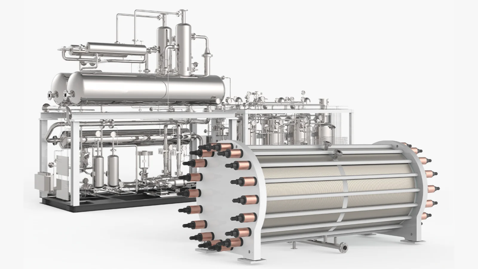
An electrolyser stack produces hydrogen, but it cannot operate as a complete plant on its own. Balance of Plant (BoP) brings together the equipment that supplies water and electrical power, manages process liquids and heat, conditions the gas, and controls the installation.
The required scope depends on the electrolyser technology, production capacity, hydrogen specification, and site conditions. Some systems are built into the manufacturer’s package; others are supplied as separate skids or site infrastructure. Defining these boundaries early helps avoid gaps between equipment suppliers and the installation team.
DM/DI Water System
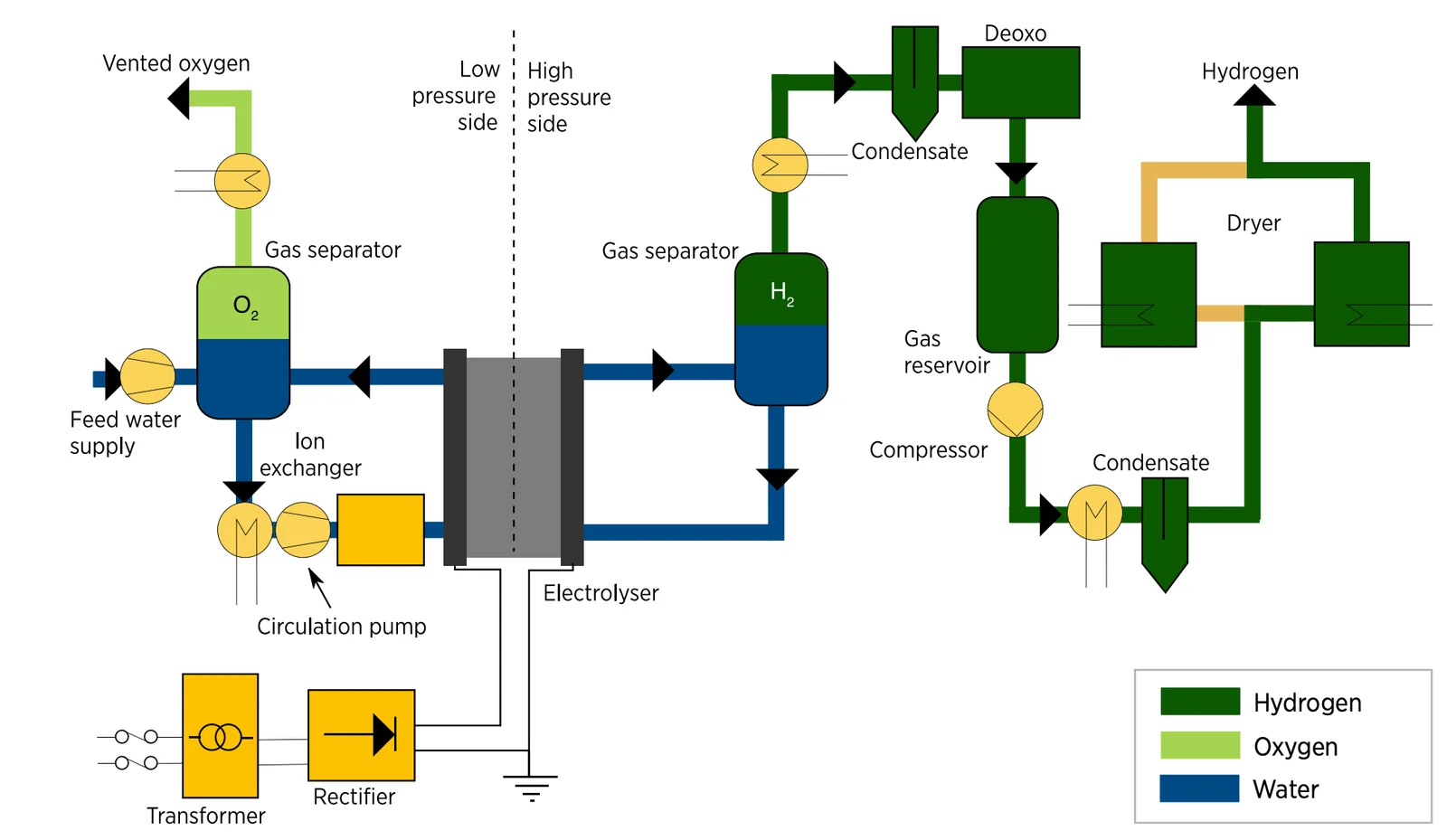
The demineralised or deionised (DM/DI) water system prepares feedwater to meet the electrolyser manufacturer’s quality requirements. Depending on the source water, treatment may include filtration, reverse osmosis, and a final deionisation or polishing stage.
The package can include treated-water storage, transfer pumps, conductivity monitoring, and distribution piping. Water quality and flow should be specified around the selected equipment, while the plant water balance should also account for treatment losses and supporting utilities.
Lye Preparation and Circulation
Alkaline electrolysers use an alkaline electrolyte, commonly potassium hydroxide (KOH) dissolved in treated water. Supporting equipment can include preparation and storage tanks, circulation pumps, filters, and heat exchangers to maintain the required electrolyte condition and flow.
Some AEM electrolysers also use a circulating dilute alkaline solution. The concentration, preparation method, and circulation arrangement depend on the manufacturer’s design. An AEM package should therefore not be assumed to need the same lye system as a conventional alkaline plant. PEM electrolysers do not use a lye circulation circuit.
Gas-Liquid Separation
Gas leaving the electrolysis process can carry water or electrolyte droplets. Gas-liquid separators, demisters, and associated return circuits separate these liquids from the gas and return them to the appropriate process loop.
Hydrogen and oxygen streams are kept separate, with level and pressure monitoring suited to the process. This stage removes bulk liquid and entrained droplets; it does not replace downstream drying or removal of trace oxygen from hydrogen.
Hydrogen Purification and Drying
The hydrogen purification unit brings the product gas to the purity and moisture specification required by the downstream application. A typical arrangement combines catalytic oxygen removal with cooling, condensate separation, and adsorption drying.
Catalytic Oxygen Removal
In a deoxygenation, or DeOxo, reactor, residual oxygen reacts with hydrogen over a suitable catalyst, such as a palladium-based catalyst, to form water:
2 H₂ + O₂ → 2 H₂O
The reaction removes oxygen but adds water to the gas stream. Cooling and condensate separation remove bulk moisture, while the dryer removes the remaining water vapour. Catalyst selection and operating conditions are defined for the feed composition and required performance.
PSA or TSA Drying
Adsorption systems use materials such as molecular sieves to capture moisture. In temperature swing adsorption (TSA), heating regenerates the adsorbent. Pressure swing adsorption (PSA), or pressure-regenerated adsorption drying, uses changes in pressure to regenerate the bed, depending on the selected package.
PSA can also be configured for broader hydrogen purification; it is not automatically equivalent to a dedicated dryer. Select the system around inlet contaminants, flow, pressure, dew point, hydrogen recovery, and continuity of supply. Product gas analysers can verify moisture and residual oxygen against the agreed specification.
Rectifier
The electrolyser requires controlled direct-current (DC) power. A rectifier converts the alternating-current (AC) electrical supply into DC at the voltage and current needed by the stack.
Selection considers the operating range, conversion losses, ripple, harmonics, cooling, protection, and control interfaces. Rectifier performance affects both stack operation and the electrical characteristics seen by the site supply.
Transformer
A transformer matches the incoming AC supply voltage to the requirements of the rectifier and other plant loads. Its rating and configuration depend on the site’s electrical connection, plant capacity, and equipment specifications.
Selection considers voltage ratio, electrical isolation where required, losses, cooling, protection, and the effects of the connected rectifier load. The transformer, rectifier, and LT/HT panels should be coordinated as part of the plant’s electrical design.
Electrical Power Supply: LT/HT Panels
Low-tension (LT) or high-tension (HT) panels receive, distribute, and protect the electrical supply as required by the site connection and plant load. The scope can include switchgear, metering, protection, motor feeders, auxiliary supplies, cables, and earthing.
Electrical planning should account for the complete plant, including pumps, cooling, purification, instrumentation, and optional downstream equipment. Protection and interfaces must be coordinated with the site’s existing electrical infrastructure.
PLC, SCADA, and Plant Controls
A programmable logic controller (PLC) coordinates start-up, normal operation, and controlled shutdown. It monitors process measurements and communicates with the rectifier, pumps, valves, purification equipment, and other package controllers.
A human-machine interface (HMI) gives operators access to equipment status and controls. A supervisory control and data acquisition (SCADA) system provides plant-wide visibility through operating screens, alarm management, historical trends, and data logging. The PLC and SCADA can communicate with equipment controllers and the site’s existing control systems, with access and integration requirements defined for the project. Safety functions requiring a separate safety-rated architecture should be defined independently of ordinary process control.
Cooling and Heat Management
The stack and supporting equipment generate heat. Heat exchangers, cooling-water circuits, or chillers maintain the operating temperatures required by the selected system. Cooling capacity, water quality, and site heat-rejection conditions should be included in the plant design.
Safety Equipment and Protective Systems
Safety-related equipment can include hydrogen leak detectors, gas-purity analysers, pressure-relief devices, ventilation, emergency stops, isolation valves, and suitable electrical equipment for the assessed environment.
These measures form part of a coordinated safety design covering operating limits, alarms, interlocks, shutdown actions, and operator procedures. Equipment selection and testing should follow the applicable requirements and manufacturer guidance for the installation.
Optional Downstream Equipment
- Compressors: Raise hydrogen pressure where the downstream process, storage, or delivery system requires it.
- Storage systems: Provide buffer capacity or stored inventory based on production, demand, and supply-continuity requirements.
- Distribution piping and manifolds: Connect production, storage, and users with the required pressure regulation, isolation, and instrumentation.
- Dispensing stations: Deliver hydrogen to the intended vehicle or equipment, with application-specific compression, storage, metering, and dispensing requirements.
- Oxygen collection and treatment: Recover the oxygen stream where there is a defined use, rather than assuming oxygen recovery is included in every plant.
Define the Complete Plant Scope
A useful BoP specification identifies what is included in the electrolyser package, what is supplied separately, and what the customer provides at site. It also defines utility requirements, equipment interfaces, acceptance criteria, and maintenance access.
NorthBridge GasTech LLP undertakes complete turnkey hydrogen projects and individual packages covering equipment, water treatment, piping, gas conditioning, electrical integration, and supporting infrastructure.
For a broader view of how these systems work together, read Balance of Plant: Integration, Performance, and Reliability.